cosmos.wikisort.org - Spacecraft
Explorer 38 (also called as Radio Astronomy Explorer A, RAE-A and RAE-1) was the first NASA satellite to study Radio astronomy. Explorer 38 was launched as part of the Explorer program, being the first of the 2 RAE-satellites. Explorer 38 was launched on 4 July 1968 from Vandenberg Air Force Base, California, with a Delta J launch vehicle.[3]
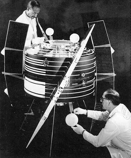 Explorer 38 satellite | |
| Names | RAE-A RAE-1 Radio Astronomy Explorer-1 |
|---|---|
| Mission type | Radio astronomy |
| Operator | NASA |
| COSPAR ID | 1968-055A |
| SATCAT no. | 03307 |
| Mission duration | 12 months (planned) |
| Spacecraft properties | |
| Spacecraft | Explorer XXXVIII |
| Spacecraft type | Radio Astronomy Explorer |
| Bus | RAE |
| Manufacturer | Goddard Space Flight Center |
| Launch mass | 602 kg (1,327 lb) |
| Power | 25 watts |
| Start of mission | |
| Launch date | 4 July 1968, 17:26:50 GMT[1] |
| Rocket | Thor-Delta J (Thor 476 / Delta 057) |
| Launch site | Vandenberg, SLC-2E |
| Contractor | Douglas Aircraft Company |
| Entered service | 4 July 1968 |
| Orbital parameters | |
| Reference system | Geocentric orbit[2] |
| Regime | Medium Earth orbit |
| Perigee altitude | 5,851 km (3,636 mi) |
| Apogee altitude | 5,861 km (3,642 mi) |
| Inclination | 120.60° |
| Period | 224.40 minutes |
| Instruments | |
| Capacitance Probe Impedance Probe Planar Electron Trap Radio Bursts Receivers Step Frequency Radiometers | |
Explorer program | |
Spacecraft
Explorer 38 spacecraft measured the intensity of celestial radio sources, particularly the Sun, as a function of time, direction and frequency (0.2 to 20-MHz). The spacecraft was gravity-gradient stabilized. The spacecraft weight was 602 kg (1,327 lb), and average power consumption was 25 watts. It carried two 230 m (750 ft) long V-antennas, one facing toward the Earth and one facing away from the Earth. A 37 m (121 ft) long dipole antenna was oriented tangentially with respect to the Earth's surface.[3]
The spacecraft was also equipped with one 136-MHz telemetry turnstile. The onboard experiments consisted of four step-frequency Ryle-Vonberg radiometers operating from 0.45 to 9.18-MHz, two multichannel total power radiometers operating from 0.2 to 5.4-MHz, one step frequency V-antenna impedance probe operating from 0.24 to 7.86-MHz, and one dipole antenna capacitance probe operating from 0.25 to 2.2-MHz. Explorer 38 was designed for a 12 months minimum operating lifetime.[3]
The spacecraft tape recorder performance began to deteriorate after 2 months in orbit. In spite of several cases of instrument malfunction, good data were obtained on all three antenna systems. The small satellite observed for months the "radio sky" in frequencies between 0.2 and 9.2-MHz, but it was subjected to the continuous radio interference coming from our planet, both natural (aurorae, thunderstorms) and artificial.[3]
Instruments
Explorer 38 has 4 antennas deployed in orbit:[4]
- Two V-shaped antennas with each of the 4 branches being 229 m (751 ft) long and used by scientific experiments;
- A 37 m (121 ft) electric dipole antenna used by scientific experiments;
- A cross-dipole turnstile antenna for the transmission of telemetry on a frequency of 137-MHz.
The scientific experiments are:
- Four Ryle-Vonberg radiometers analyzing frequencies between 0.45 and 9.18-MHz;
- Two multi-channel radiometers analyzing frequencies between 0.2 and 5.4-MHz;
- An impedance probe associated with 5 antennas analyzing frequencies between 0.24 and 7.86-MHz;
- A capacitance probe associated with the dipole antenna analyzing frequencies between 0.25 and 2.2-MHz.[4]
Experiments
Capacitance Probe
Determine reactive and resistive components of antenna impedance as a function of local electron density, electron temperature, magnetic field, and vehicle potential. The impedance measurements was made at 10 frequencies (0.25 to 8-MHz).[5]
Impedance Probe
Determine reactive and resistive components of antenna impedance as a function of local electron density, electron temperature, magnetic field, and vehicle potential. The impedance measurements was made at ten frequencies (0.25 to 8-MHz).[6]
Planar Electron Trap
There were two planar electron traps mounted on opposite sides of the spacecraft. The trap consisted of a collector, positively biased in order to repel incoming ions and to reduce photoemission of electrons from the collector. A sawtooth voltage was applied to a grid, and the resulting current to the collector was telemetered. Electron density was obtained by analysis of the grid voltage-collector current profile. The electron density representing the ambient value was that obtained from the probe facing the direction of satellite motion. The spacecraft attitude for this purpose was determined either from the electron density or from the solar and magnetic sensors on the spacecraft. The data were tape recorded and telemetered once each orbit. These sensors operated nominally since launch and were providing electron density mapping data at spacecraft altitude.[7]
Radio Bursts Receivers
Thirty-two channel step frequency radiometers were connected to the lower 230 m (750 ft)-long antenna and to the 37 m (121 ft)-long dipole via high-impedance preamplifiers. The burst radiometer on the dipole was stepped rapidly through 32 discrete frequencies between 0.2 and 5.4-MHz to generate dynamic spectra. The radiometers measured the amplitude, rate of change of frequency, and decay time of solar burst and other rapidly varying noise in the 0.2 to 5.4-MHz band. Operating in two sensitivity modes, these receivers could measure signals up to 50 dB above the cosmic background level. The 32 channels were cycled every 7.7-seconds. The chief advantages of the burst radiometers were high time resolution and relatively few components for high reliability. The radiometer was a simple total-power receiver consisting of an input balun, a power divider, and several parallel tuned-radio-frequency strips. After about 18 months of operation, one of the preamplifiers on the lower V burst radiometer failed, reducing the sensitivity and changing the antenna pattern for that radiometer.[8]
Step Frequency Radiometers
This experiment used four Ryle-Vonberg radiometers connected to the three spacecraft antennas to provide high accuracy and long-term stability necessary for the sky mapping over many months of operation. One was connected to the 37 m (121 ft) dipole, one to the lower 230 m (750 ft) V-antenna, and two to the upper V-antenna. The Ryle-Vonberg radiometers used on the V-antennas were connected via balun transformers that provided an approximate match to the antenna impedance. Each radiometer was successively tuned to nine different frequencies in the band 0.48 to 9.18-MHz. Precise, automatic, and continuous calibration was inherent in this type of design. The intensities of celestial radio sources were measured by this experiment. The "fine" output channel of the Ryle-Vonberg radiometers failed after 3 to 9 months of operation. The Ryle-Vonberg "coarse" output channels provided good data without interruption, however.[9]
Results
The following results are reported in 1971:
- Absolute spectrum and average cosmic noise up to the frequency 0.5-MHz.
- Collection of radio data transmitted during type III solar radio bursts in the 0.2 to 5-MHz frequency band. These elements made it possible to obtain a first estimate of the solar corona electron density gradient, the solar wind speed and density inhomogeneities in the solar corona regions between 10 and 30 solar radiis. A second radio broadcast of hectometric frequency was observed.
- An upper limit to the radio flux emitted by Jupiter's High frequency (HF) radio broadcasts was determined by the observations made during the Moon's occultations of the giant planet.
- Radio emissions from the Earth of natural and human origin are both widespread and often very intense (40 dB higher than the cosmic background) on the frequencies observed (0.2 to 9.2-MHz).[4]
See also
- Explorer 49
- Explorer program
References
- McDowell, Jonathan (21 July 2021). "Launch Log". Jonathan's Space Report. Retrieved 13 November 2021.
- "Trajectory: Eplorer 38 (RAE-A) 1968-055A". NASA. 28 October 2021. Retrieved 13 November 2021.
 This article incorporates text from this source, which is in the public domain.
 - "Display: Eplorer 38 (RAE-A) 1968-055A". NASA. 28 October 2021. Retrieved 13 November 2021. This article incorporates text from this source, which is in the public domain.
- J. K. Alexander, L. W. Brown and T. A. Clark (June 1970). "The spectrum of the extra-galactic background radiation at low radio frequencies" (PDF). Nature. NASA. 228 (5274): 847–849. Bibcode:1970Natur.228..847C. doi:10.1038/228847a0. hdl:2060/19700019438. PMID 16058725. S2CID 4148391. Retrieved 13 November 2021.
{{cite journal}}: CS1 maint: uses authors parameter (link) - "Experiment: Capacitance Probe". NASA. 28 October 2021. Retrieved 13 November 2021. This article incorporates text from this source, which is in the public domain.
- "Experiment: Impedance Probe". NASA. 28 October 2021. Retrieved 13 November 2021. This article incorporates text from this source, which is in the public domain.
- "Experiment: Planar Electron Trap". NASA. 28 October 2021. Retrieved 13 November 2021. This article incorporates text from this source, which is in the public domain.
- "Experiment: Radio Bursts Receivers". NASA. 28 October 2021. Retrieved 13 November 2021. This article incorporates text from this source, which is in the public domain.
- "Experiment: Step Frequency Radiometers". NASA. 28 October 2021. Retrieved 13 November 2021. This article incorporates text from this source, which is in the public domain.
External links
- Real Time Satellite Tracking and Predictions: Explorer 38 (RAE-A) N2YO.com
- Data cisplays of Radio Astronomy Explorer-1
Explorers Program | |||
|---|---|---|---|
List of Explorers Program missions | |||
| Missions | |||
| Proposals |
| ||
| |||
Другой контент может иметь иную лицензию. Перед использованием материалов сайта WikiSort.org внимательно изучите правила лицензирования конкретных элементов наполнения сайта.
WikiSort.org - проект по пересортировке и дополнению контента Википедии